Click on the image for a larger photo
Click on the image for a larger photo
Click on the image for a larger photo
Click on the image for a larger photo
Click on the image for a larger photo
RIGGING YOUR DT LINE
One of the most common questions we see is how to rig the stabilizer for the remote DT line from our timers. Larry Davidson of Moneta, VA is a very successful competition flier and a good customer. He has generously provided a set of photos that details how he does it. The plane in the example is an ignition powered Alert with our Ultimate OT timer. However, the methods and techniques shown are applicable to any of our timers with a DT function, and most planes, regardless of size or power. Obviously, there are changes one can make to suit individual preferences and particular aircraft.
Since a number of high resolution photos are involved, we show smaller thumbnail photos on this page to keep the load time down. To view larger photos with more details, simply click on any of the photos, and use the "Back" button on the new page to return to here.
OVERVIEW
Larry uses 50 pound test Dacron® fish line for his DT. (20 pound line for .20 and under planes) He uses a DT limit stop on the fuselage to stop the line after release so the correct stabilizer angle (about 40-45 degrees - refer to your plans) is achieved. He makes a 90 degree bend in 3/32" OD aluminum tubing (from K&S) to convert the line running parallel to the fuselage to to one going up through the trailing edge of the stab. NOTE: in these photos the aluminum tubing is outside the fuselage. Some will prefer to have it inside. The choice is yours, but keep in mind how you will replace the line when needed. Rather than a rubber band for line tension, Larry uses a coil spring that he makes himself from 0.020 music wire. To minimize the shock when the spring hits the limit stop, Larry slides a piece of silicone tubing on the line between the spring and limit stop. The "T" used on the stab end to hold the TE down is slid through the hole in the stab during preparation of the model for flight. The photos should answer any questions you have.
To see how the DT line is attached to the timer post, click here.
|
|
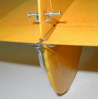
This shows the stab in the held down position. Tension is on
the line going to the timer. The keys to hold the stab in alignment when
down is just visible on the bottom. Click on the image for a larger photo |
|
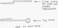
This is a drawing of the hold down wire that is firmly
attached to the stab TE. In this case Larry trapped the wire under the
rudder and then used epoxy. A rudder to trap it will not be present on all
planes, so use of a plywood "sandwich" with epoxy might be called for.
You might also have the line inside the fuselage and come up directly under
the TE. Then, you would use a piece of ply to give a hard surface for
the ":T" to sit on. In
any event, make it strong (but light)! Click on the image for a larger photo |
|
|
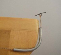
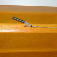
This shows the 3/32" OD
aluminum tubing used to feed and guide the line to the stab TE. He uses a
square knot to tie the line, with a drop of CyA to lock it. Click on the image for a larger photo
|
|
This shows the stab in the up or DT position. The travel is
limited by the line stop on the fuselage. If one does not want to use a line
stop, then a separate limit line would need to be used at the tail. NOTE:
some plane designs have a "built-in" limit on the stab travel, so no other
limit is needed.
Click on the image for a larger photo |
|
|
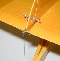
This shows the limit stop attached to the fuselage just to
the right of the timer. The spring is self-made. from .020 music wire. The
silicone tubing is used as shock absorber. (The material used is
actually the fuel line we sell.) Click on the image for a larger photo |
Click on this button to go to our main Helpful Hints page
![]()
OR
Use your browser back function to return to the page that brought you here.